Soil Moisture Sensors
June 26th, 2022, last changes on July 4th, 2022note this post is still being improved: additional measurements are to be done
Each time I buy these capacitive soil moisture sensors, I get a slightly different thing. Most of the simply do not work and here is the answer why.
Forget about any confidence that by ordering a version, say 1.2, you get the version 1.2. It's really random.
The principle of the sensor is very simple:
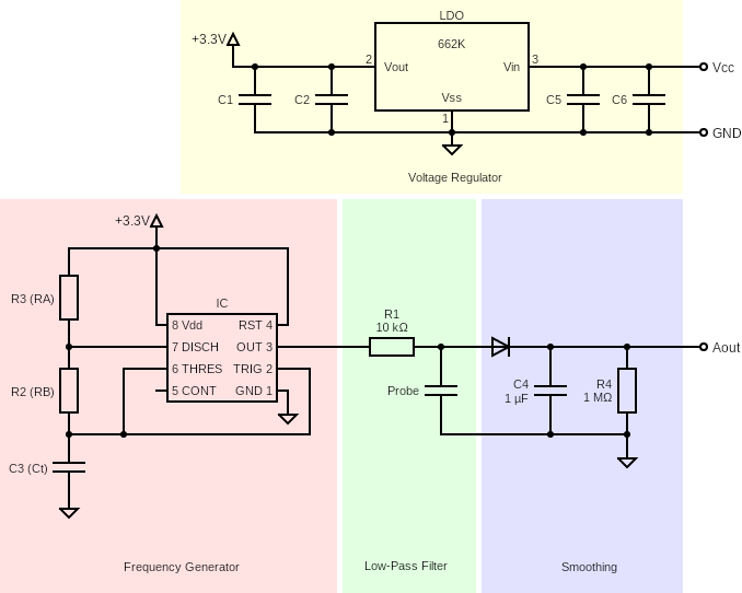
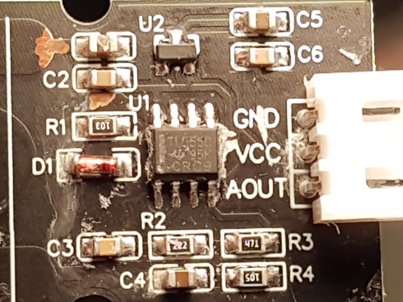
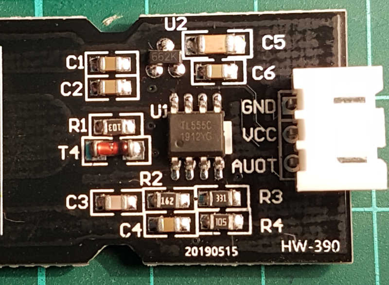
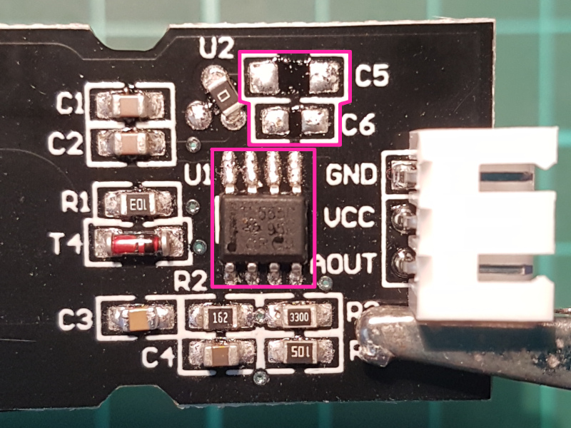
It consists of four function blocks:
- Voltage Regulator, making it universal for 3.3V and 5V setups (well, if it would have been designed correctly).
- Frequency Generator, based on the 555-family timers, producing a squarish-like wave.
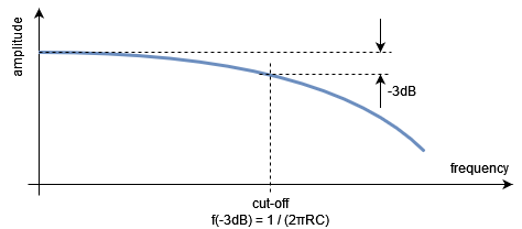
- Low-Pass Filter, and this is the place, where the actual sensor comes in place.
- Smoothing filter to get a DC signal that one can measure (otherwise one would get a random value out of a simple ADC converter).
| Component | v.1.2 with LDO | v.2.0 with LDO | v.1.2 without LDO |
|---|---|---|---|
| R1 (LPF) | 10 kΩ | 10 kΩ | 10 kΩ |
| R2 (Rb*) | 2.2 kΩ | 1.6 kΩ | 1.6 kΩ |
| R3 (Ra*) | 470 Ω | 330 Ω | 330 Ω |
| R4 (Smoothing) | 1 MΩ | 1 MΩ | 1 MΩ |
| C1 (LDO out) | . | . | . |
| C2 (LDO out, chip protection) | 89-93 nF | . | . |
| C3 (Ct*) | 120 pF | 13-17 pF | 680-830 pF, maybe 770 pF |
| C4 (Smoothing) | . | . | . |
| C5 (LDO in) | . | 98 nF | 7.3-8.6 μF |
| C6 (LDO in) | 94 nF | 100-101 nF | 89-103 nF |
| calculated frequency** | 2.5 MHz | 27 MHz*** | 530 kHz |
| measured frequency | 263 kHz**** | 1.5 - 1.6 MHz (avg 1.6 MHz) | 359 - 788 kHz (avg 423 kHz) |
Please note, I don't have a reliable way of measuring the capacitors at the moment, maybe will update it one other day.
* The Ra, Rb and Ct values determine the wave's frequency and ratio.
** Based on the measured C3 value, which may be quite off.
*** This value is way beyond what a 555-chip is able to deliver. Additional reason of the faulty operation?
**** The only explanation for this value being so much off the calculated one is that the only C3 I've got to get measured has been partially damaged while desoldering.
f = 1.44 / ( (Ra + 2 * Rb) * Ct )
=> Ct = 1.44 / ( f * (Ra + 2 * Rb) )
Calculated (as I don't trust my multimeter) values of the Ct capacitors for two common frequencies (see below to understand why the value) in accordance to the resistors found on the PCBs:
| 370 kHz | 1.5 MHz | |
|---|---|---|
| Ra = 470 Ω and Rb = 2.2 kΩ | ~ 800 pF | ~ 200 pF |
| Ra = 330 Ω and Rb = 1.6 kΩ | ~ 1 nF | ~ 270 pF |
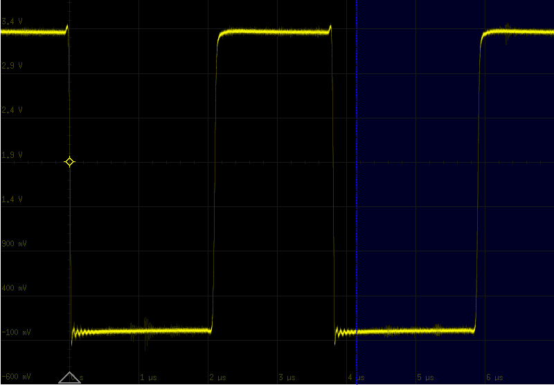
555-timer's output of v.1.2 with LDO at 5V
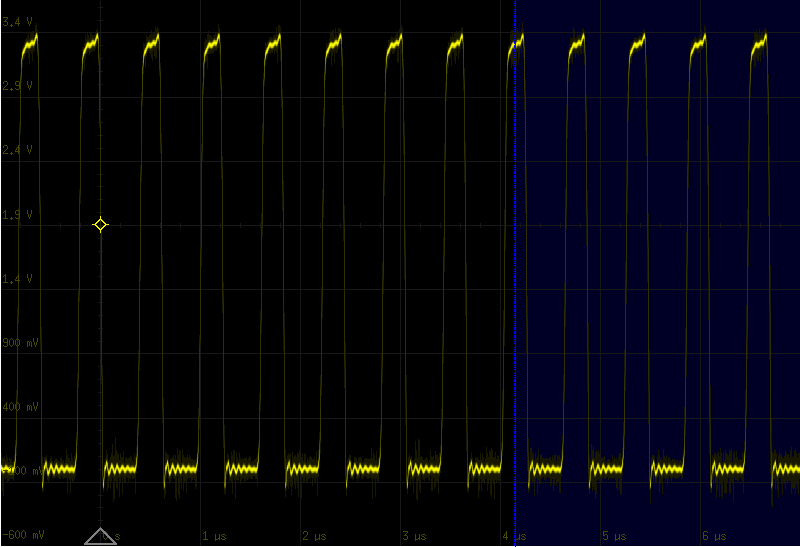
555-timer's output of v.1.2 with LDO at 5V
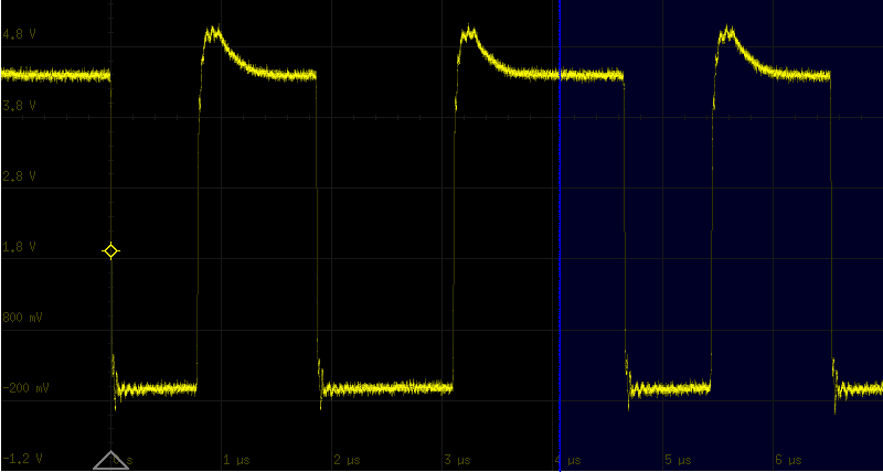
555-timer's output of v.1.2 with LDO at 5V
What are the problems?
- Each LDO requires a slightly higher voltage than the one to be available on the output. The difference between those two is the drop-out voltage. Accordingly to one of the XC6206P332MR specs a typical value is of 75mV and a maximum of 350mV. So, typically you have to deliver a least 3.375V if you want to get 3.3V out. For higher current values even 3.65V.
- Some of the PCBs does not have the LDO at all, but they keep the capacitors that are required for the LDO to work. It's not an issue, but just that you are aware of that.
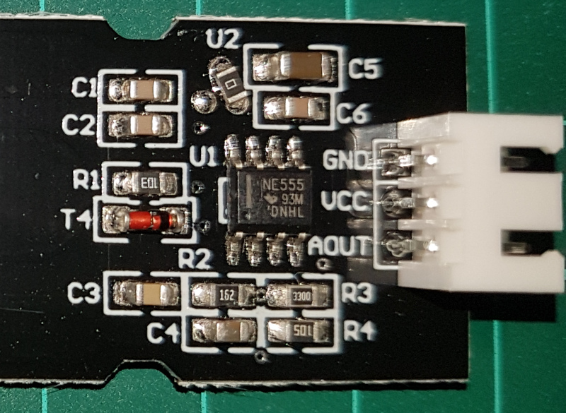
- The issue is, the 555-timers sometimes are the TL555C-series (good for voltages from like 1.8V or 2V up to 15V) and sometimes are the NE555-series (requiring at least 4.5V to work at all). And guess what: yes, there are PCBs incorporating both, the LDO for 3.3V and the NE555-timer! There will be nothing on the output as this chip does not do anything with that low voltage.
- Next issue is design of the low-pass filter together with the frequency of the generated wave. The idea of the sensor is: depending on the capcitance of the environment (soil, air, water), the low-pass filter moves its cut-off frequency lower/higher, so that the observed voltage goes lower/higher as a consequence. As you know, RC-filters do not cut frequencies off like a knife. They gradually attenuate the signal as the frequencies go beyond the cut-off one. The Cave Pearl Project assumes sensor's characteristics to be like 30 pF of capacitance in the air and up to 400pF in the water. My measurements on the v1.2 (with LDO) PCB show the range 7 pF (air) to 1260 pF (water). Anyway, with the R1 of a value of 10 kΩ, we get a cut-off frequencies as follows:
| C | f |
|---|---|
| 7 pF | 2.274 MHz |
| 30 pF | 530 kHz |
| 400 pF | 40 kHz |
| 1260 pF | 13 kHz |
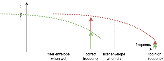
It means, the generated signal should be somewhere in this range to make it work (probably close to the frequency for the dry soil). And guess what: yes, they don't match! The original design of the sensor (as the Internet says) was to produce 370kHz. The new design v.1.2 changed it to like 1.5MHz (my own measurements confirm it to be about 1.6MHz for the v1.2 with LDO PCB). However, the latest v2.0 version delivers low values just by a few drops of water and almost no difference as the amount of water changes. They increased the frequency of the signal to improve stability (for as far as I may guess, in order to limit the influence of salts in water). And guess what: yes, the filter has not been adapted for that! This setup leads to more noise than real data.
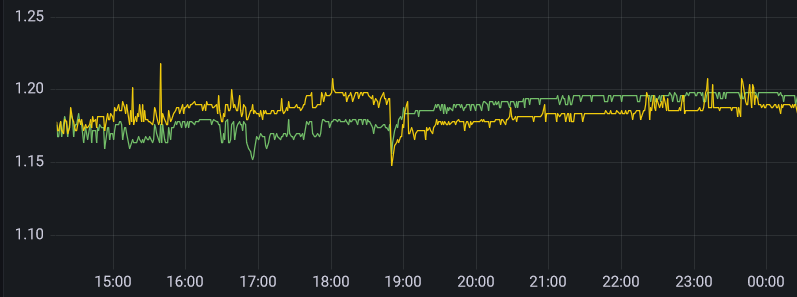
The above graph shows readouts of two v.2.0 sensors and watering (both) at 6:50 p.m. As you see - hard to distinguish the readouts from the noise.
How to make it work?
Well, there are a few ways to go. My first approach was to take the new PCBs marked as v.2.0, because I work with 3.3V and they contain the TL55C low-voltage timer, and do the following:
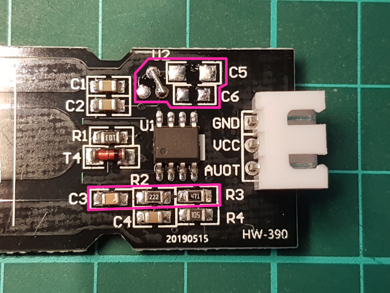
- Remove the LDO (don't forget to jump the Vin and Vout pads, otherwise the timer will not get powered). Keep the C2 in place, as it protects the timer. The C1, C5 and C6 do not have any function now, they can get removed, but they don't hurt.
- Change C3, R2 and R3 to the values known from the v.1.0 version (C3 = ca. 800 pF - value not verified!, R2 = 2.2 kΩ, R3 = 470 Ω).
Update: second approach was to exchange the LM555 to TL555C on the PCB v.1.2 without an LDO (same reason: to be able to work with 3.3V). I have removed C5 and C6 - however same story: they don't hurt and may stay there. I wasn't sure what the value of the C3 is, so used the opportunity to desolder it temporarily and measure it (my multimeter is very bad at measuring capacities in-circuit). It seems, the frequency should be in the 500-kHz-area. The exact measurement comes later...
As you can see below, the response of the latter modification is much better: significant difference between different water levels.
Measurements
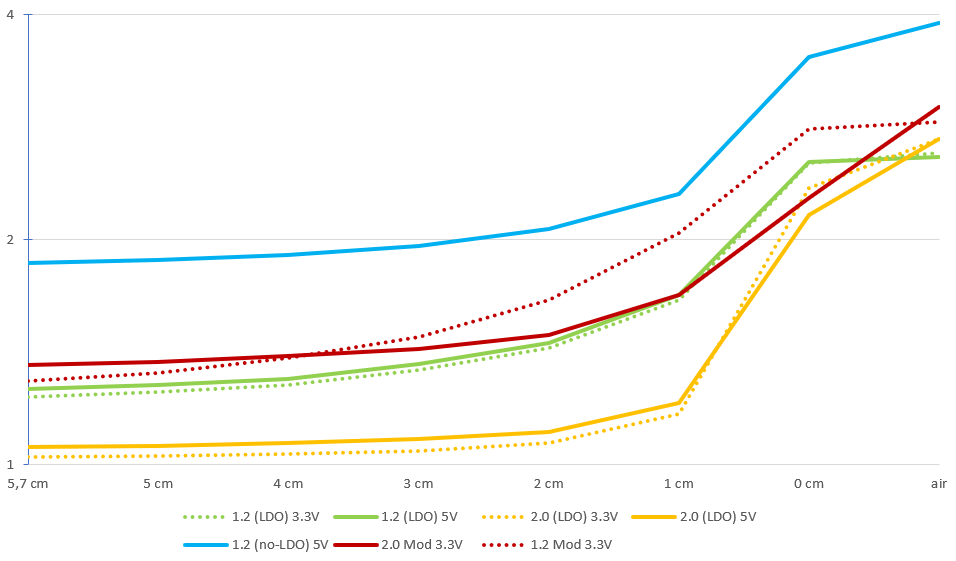
In the table below you may see measured voltage levels depending on the water level for some of the PCB variants, as well as the ratio to the previous voltage level to better see the issues.
Version 1.2 including the 3.3V-LDO and working in kHz-range.
Version 2.0 including the 3.3V-LDO and working in MHz-range (mismatch with the filter)
Version 1.2 without an LDO, seems to be working in MHz-range (not yet measured)
Modified (first approach) version 2.0 from above (removed LDO and modified working frequency)
Modified (second approach) version 1.2 without an LDO (exchanged LM555 to TL555C)
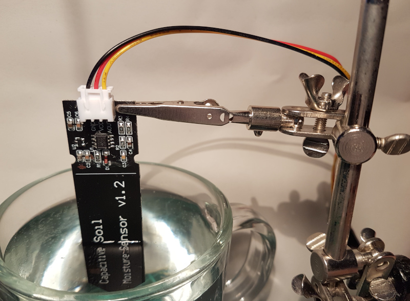
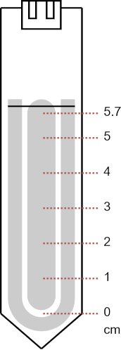
How the water levels have been measured
| Water level | v.1.2 LDO on 3.3V | v.1.2 LDO on 5V | v.2.0 on 3.3V | v.2.0 on 5V | v.1.2 no-LDO on 5V | My Mod 1 on 3.3V | My Mod 2 on 3.3V |
|---|---|---|---|---|---|---|---|
| 5.7 cm | 1.232V | 1.262V | 1.024V | 1.057V | 1.859V | 1.360V | 1.292V |
| 5 cm | 1.250V (+1.5%) | 1.278V (+1.3%) | 1.027V (+0.3%) | 1.059V (+0.2%) | 1.876V (+0.9%) | 1.373V (+1%) | 1.328V (+2.8%) |
| 4 cm | 1.279V (+2.3%) | 1.302V (+1.0%) | 1.034V (+0.7%) | 1.068V (+0.8%) | 1.906V (+1.6%) | 1.396V (+1.7%) | 1.389V (+4.6%) |
| 3 cm | 1.337V (+4.5%) | 1.362V (+4.6%) | 1.044V (+1.0%) | 1.081V (+1.2%) | 1.963V (+3.0%) | 1.430V (+2.4%) | 1.484V (+6.8%) |
| 2 cm | 1.432V (+7.1%) | 1.456V (+6.9%) | 1.068V (+2.3%) | 1.105V (+2.2%) | 2.066V (+5.2%) | 1.491V (+4.3%) | 1.66V (+12%) |
| 1 cm | 1.662V (+16%) | 1.687V (+16%) | 1.169V (+9.5%) | 1.208V (+9.3%) | 2.301V (+11%) | 1.684V (+13%) | 2.04V (+23%) |
| 0 cm | 2.532V (+52%) | 2.539V (+51%) | 2.346V (+101%) | 2.16V (+79%) | 3.511V (+52%) | 2.276V (+35%) | 2.815V (+38%) |
| air | 2.61V (+3.1%) | 2.58V (+1.6%) | 2.73V (+16%) | 2.73V (+26%) | 3.9V (+11%) | 3.01V (+32%) | 2.873V (+2.1%) |