Digital Watering System
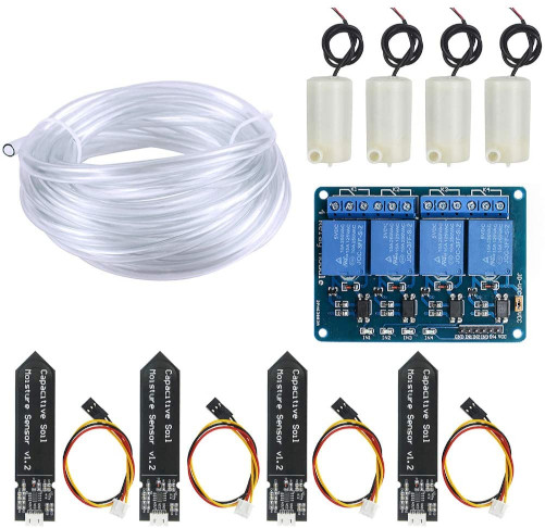
July 22nd, 2021, last changes on June 26th, 2022I've found a very cheap set of capacitive soil moisture sensors and water pumps, plus relais and some plastic pipes:

There are thousands of offers of single pumps or sensors, but by way not as cheap as this set (28€). Customer reviews are pretty negative: each part differs from the description/depiction, wrong chips, "it does not work", but who cares - the price is inviting!
The delivered package did contain even one more pump than promised and an additional meter of the pipes. The pipes stink of something artificial. Not bad, but annoying.
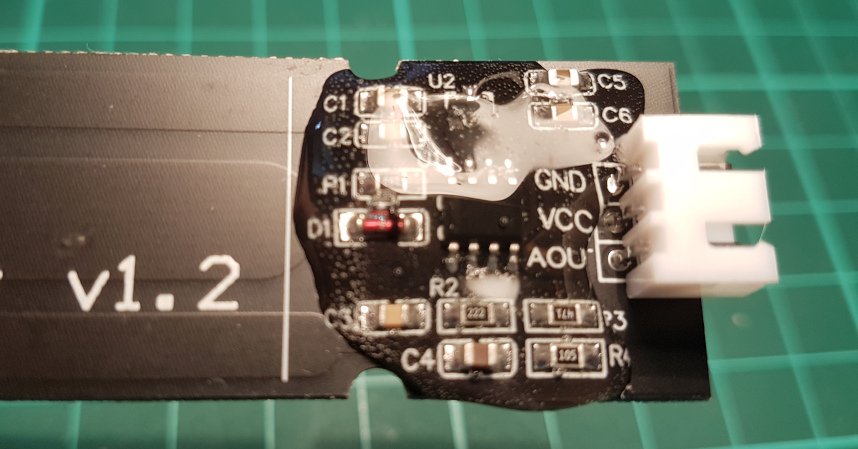
The most interesting part for me were the sensors. Their sensing part is painted, so no oxidation should take place. Anyway, the electronics is unprotected, which is a source of problems (read below).

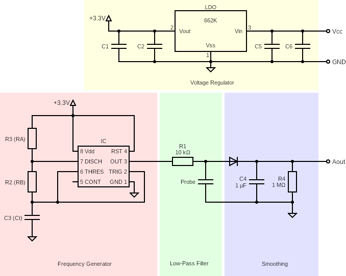
edit Previously, I have referenced schematics from the Cave Pearl Project. Now, a new schematics is in place. There are some differences I have identified: the pin no. 5 (CONTrol voltage terminal) is not wired and the capacitors C1 and C2 are rather a part of the voltage regulation circuit. Resistor (R2, R3) and capacitor (C3) values seem to differ from mod to mod of the PCB. The role of the low-pass filter has been incorrectly presented. See my new article that goes into details on this.
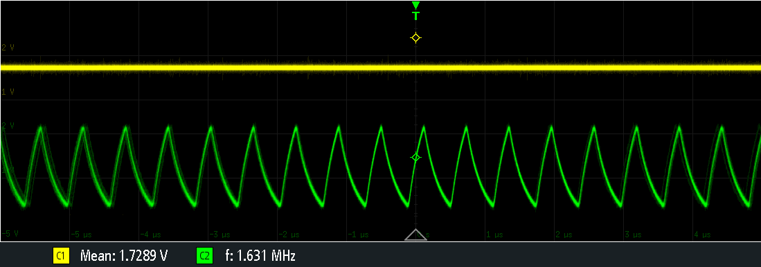
It wasn't quite clear to me, whether the analog signal is stable or growing with each timer iteration (as the design is based on a timer chip 555C). The latter would be a no-go for a simple ADC (analog-digital converter). A short check on an oscilloscope reassured myself: a clean stable voltage level, reacting immediately on surrounding amount of water.

C1 connected to the output. C2 connected to the R1 resistor.
It took a while to create a nice setup, to put the sensors into flowerpots, to lay the pipes and stuff. I'm powering the sensors with a 3.3V source and these are the first findings:
- All sensors are very similar in their characteristics. 100% water gives 2.64 - 2.74V output, while hanging-in-the-air 1.24 - 1.29V output.
- The readout stability over days is poor. As you see, the usable voltage range is quite narrow (1.5V in best case), so it makes a big difference for the watering algorithm whether you set 0.1V more or less as the threshold. Unfortunately, the daily deviation is even more than these 0.1V. So absolute values for an automated watering system are quite unrealistic.
- The naked electronics is - as expected - very sensitive to the environmental influence. Even a single water drop changes the readout significantly.
The pumps, although very cheap, do their work. I get like 1 liter in 50 seconds and the length of the pipe does not really influence it. They generate quite a lot of electromagnetic noise. Although I use a separate power source and no common ground for powering the pumps, the nearby Raspberry experiences transmission errors on a 5 cm long I2C line to/from an ADC (at 100kbaud).
Improvements
Electromagnetic noise
Just add a capacitor of 10nF - 100nF as close to the motor as possible (between GND and power line only, as as the frame is completely insulated by the plastic housing). This solved any data transmission issues I have experienced before.
Naked electronics
The Internets say, you should fill it with epoxy. As I did not have it at hand, I've decided to pour hot melt glue on the naked circuit. It was not a good idea, because the glue shrinks while cooling down slightly. Due to the temperature, the glue seems to move some of the components in the cool-down process. Although it is as little as not visible by a naked eye, some of the connection get damaged this way. I've managed to repair the sensors by heating the glued area with hot air again, but the resilience of the solution is questionable.

Next try was to put it as a whole into a shrink insulation tube. As you see, a few reduction steps were required to meet the diameter of the cable. The obvious disadvantage is the limited sensitivity of the sensor.

Update to the schematics
As the project continued growing, I needed additional sensors. This time I've got a 2.0 version of them. Some of the capacitors/resistors are different. Since it's impossible for me to measure the capacitors in-circuit, I can't tell the exact difference. Anyway, the voltage range along the axis dry-wet is sightly different. Did not observe any other differences. Still, it is very interesting, what Caffeine Owl has found out. Namely, this circuit is not supposed to work at all :). At least not with the values in the official schematics.
Update after one year of operation
The sensors did not suffer any further damages, although one of them shows some air bubbles under the protecting paint. The problematic component are the pumps. They are not really well protected against the water. Most of the motors got rusted inside and stopped rotating. Still, for this little money one season was a good result.