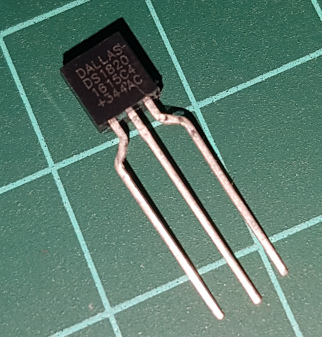
DS18S20 Temperature Sensor
December 2nd, 2021
I believe there is a mistake in calculation of the fine part of the temperature value as received from 1-Wire DS18x20-family sensors in the linux driver. The current implementation does indeed follow the official datasheet, but exactly the datasheet seems to be incorrect in this place.
DS18S20 Datasheet says two different things on the Page 6:
First:
Resolutions greater than 9 bits can be calculated using the data from the temperature, COUNT REMAIN and COUNT PER °C registers in the scratchpad. Note that the COUNT PER °C register is hard-wired to 16 (10h). After reading the scratchpad, the TEMP_READ value is obtained by truncating the 0.5°C bit (bit 0) from the temperature data (see Figure 4).
And then:
"The extended resolution temperature can then be calculated using the following equation: TEMPERATURE = TEMP_READ - 0.25 + (COUNT_PER_C - COUNT_REMAIN) / COUNT_PER_C
The last one is the formula that is implemented in the linux driver. I have performed live tests with DS18S20 sensors to verify it, how they behave. I was lowering the temperature in slow steps to see individual transitions. Below is the result.
(value), 1 (sign), 6 (count remain) and 7 (count per degC)
| Response bytes 0 value : 1 sign :: 6 count rem : 7 count per degC |
Byte 0 binary | Fraction = Byte 7 minus Byte 6 |
Bits 7..1 of Byte 0 Bits 3..0 of Fraction |
Hex | Multiplied by 1/16°C |
|---|---|---|---|---|---|
| 37:00::04:10 | 0011 0111 | 0C = 1100 | 0011011.1100 | 1BC | 27.75 |
| 37:00::05:10 | 0011 0111 | 0B = 1011 | 0011011.1011 | 1BB | 27.6875 |
| 37:00::06:10 | 0011 0111 | 0A = 1010 | 0011011.1010 | 1BA | 27.625 |
| 37:00::07:10 | 0011 0111 | 09 = 1001 | 0011011.1001 | 1B9 | 27.5625 |
| 37:00::08:10 | 0011 0111 | 08 = 1000 | 0011011.1000 | 1B8 | 27.5 |
| 36:00::09:10 | 0011 0110 | 07 = 0111 | 0011011.0111 | 1B7 | 27.4375 |
| 36:00::0A:10 | 0011 0110 | 06 = 0110 | 0011011.0110 | 1B6 | 27.375 |
| 36:00::0B:10 | 0011 0110 | 05 = 0101 | 0011011.0101 | 1B5 | 27.3125 |
| 36:00::0C:10 | 0011 0110 | 04 = 0100 | 0011011.0100 | 1B4 | 27.25 |
| 36:00::0D:10 | 0011 0110 | 03 = 0011 | 0011011.0011 | 1B3 | 27.1875 |
| 36:00::0E:10 | 0011 0110 | 02 = 0010 | 0011011.0010 | 1B2 | 27.125 |
| 36:00::0F:10 | 0011 0110 | 01 = 0001 | 0011011.0001 | 1B1 | 27.0625 |
| 36:00::10:10 | 0011 0110 | 00 = 0000 | 0011011.0000 | 1B0 | 27 |
| 35:00::01:10 | 0011 0101 | 0F = 1111 | 0011010.1111 | 1AF | 26.9375 |
| 35:00::02:10 | 0011 0101 | 0E = 1110 | 0011010.1110 | 1AE | 26.875 |
| 35:00::03:10 | 0011 0101 | 0D = 1101 | 0011010.1101 | 1AD | 26.8125 |
| 35:00::04:10 | 0011 0101 | 0C = 1100 | 0011010.1100 | 1AC | 26.75 |
| 35:00::05:10 | 0011 0101 | 0B = 1011 | 0011010.1011 | 1AB | 26.6875 |
| 35:00::06:10 | 0011 0101 | 0A = 1010 | 0011010.1010 | 1AA | 26.625 |
| ... | ... | ... | ... | ... | ... |
| 00:00::0E:10 | 0000 0000 | 02 = 0010 | 0000000.0010 | 002 | 0.125 |
| 00:00::0F:10 | 0000 0000 | 01 = 0001 | 0000000.0001 | 001 | 0.0625 |
| 00:00::10:10 | 0000 0000 | 00 = 0000 | 0000000.0000 | 000 | 0 |
| FF:FF::01:10 | 1111 1111 | 0F = 1111 | 1111111.1111 | FFF | -0.0625 |
| FF:FF::02:10 | 1111 1111 | 0E = 1110 | 1111111.1110 | FFE | -0.125 |
| ... | ... | ... | ... | ... | ... |
| FC:FF::0F:10 | 1111 1100 | 01 = 0001 | 1111110.0001 | FC1 | -1.9375 |
| FC:FF::10:10 | 1111 1100 | 00 = 0000 | 1111110.0000 | FC0 | -2.0000 |
| FB:FF::01:10 | 1111 1011 | 0F = 1111 | 1111101.1111 | FBF | -2.0625 |
My findings are confirmed by other people, e.g. here: electro-tech-online
The only unclear thing for me is the Byte 7. The datasheet says it is hard wired to 10h. The guy here says, he has seen devices with other dividers: electro-tech-online
I noticed that the count divisor was not equal to 16 as the data sheet indicated it would be. In fact, as the temperature was raised and lowered, the count divisor would increase and decrease in value (not fixed).
Assuming the guy did not make any mistake, it would be interesting to know, whether the divisor is always a power of 2 (which would make the conversion easy) or can be of any value.
Helpful in answering the question may be the datasheet of the original DS1820 sensor (without the 'S'), especially the section "OPERATION – MEASURING TEMPERATURE". The operation of the sensor can be simplified as follows: there is an RC-oscillator circuit of a frequency dependent on the temperature. The number of oscillations is counted within a time window (gate period). The "count remain" is the value that remains after the gate has been closed. As we know how many cycles do correspond to a single degree, we can calculate this fraction easily. The document says, the oscillator has a non-linear characteristics over the temperature and must be therefore compensated. This clarifies the dynamic value of the "count per degree" field. Maybe future releases of the sensor introduced a linear oscillator and fixed the value to 10h?
Next: SanDisk SecureAccess AES 1024bit